
Что такое поршневой режим?
Это режим, при котором ВСЯ поверхность диффузора ГГ движется как одно целое.Очень удобно пояснить это понятие на примере широкополосной ГГ. В области НЧ скорость изменения фазы сигнала в звуковой катушке меньше скорости распространения механического возбуждения в материале диффузора и последний ведет себя как единое целое, т.е. колеблется как поршень. На этих частотах частотная характеристика ГГ имеет гладкую форму, что свидетельствует об отсутствии парциального возбуждения отдельных участков диффузора.Обычно разработчики ГГ стремятся расширить область поршневого действия диффузора в сторону ВЧ путем придания специальной формы образующей конуса. Для правильно сконструированного целлюлозного диффузора область поршневого действия может быть приблизительно определена как длина волны звука, равная длине окружности диффузора в основании конуса. На средних частотах скорость изменения фазы сигнала в звуковой катушке превышает скорость распространения механического возбуждения в материале диффузора и в нем возникают волны изгиба, диффузор уже не колеблется как единое целое. На этих частотах показатель затухания механических колебаний в материале диффузора еще недостаточно велик и колебания, достигая диффузородержателя, отражаются от него и распространяются по диффузору обратно в сторону звуковой катушки.В результате взаимодействия прямых и отраженных колебаний в диффузоре возникает картина стоячих волн, образуются участки с интенсивным противофазным излучением. При этом на частотной характеристике наблюдаются резкие нерегулярности (пики и провалы), размах которых может достигать у не оптимально сконструированного диффузора десятка дБ.На ВЧ показатель затухания механических колебаний в материале диффузора возрастает и стоячие волны не образуются. Вследствие ослабления интенсивности механических колебаний, излучение высоких частот происходит преимущественно областью диффузора, прилегающей к звуковой катушке. Поэтому для увеличения воспроизведения ВЧ применяют рупорки, скрепленные с подвижной системой ГГ. Для уменьшения неравномерности АЧХ в массу для изготовления диффузоров ГГ вносят различные демпфирующие (увеличивающие затухание механических колебаний) присадки.
Bass Reflex vs Acoustic Suspension FAQs
Although bass reflex systems are far more popular, there’s no right or wrong choice. It all boils down to what you want your system to do. Do you prefer loud sound or accurate audio? But before making your decision, here are the most frequently asked questions about the bass reflex vs acoustic suspension;
- Bass reflex vs sealed. Which one is better? – Both systems have their advantages and disadvantages. In the end, it depends on what you want from yours. Loudness or accuracy? Would you like big or small enclosures? Answer these questions to make the right decision.
- Is bass reflex good? – Bass reflex is deemed more efficient than an acoustic suspension because it allows bass extension at a higher volume. On the other hand, an acoustic suspension lowers the bass distortion. It also has a low resonance frequency.
You may also like learn Which Helps in Getting Better Sound? Read: Digital Amp vs. Analog Amp
Advantages
A small plastic Harman Kardon powered computer speaker with a bass reflex port.
Novak concluded that a bass reflex enclosure can have greater acoustic output for a given amount of distortion, lower total harmonic, intermodulation, and transient distortion than a completely closed-box of similar size. Such a resonant system augments the bass response of the driver and, if designed properly, can extend the frequency response of the driver/enclosure combination to below the range the driver would reproduce in a similarly sized sealed box. The enclosure resonance has a secondary benefit in that it limits cone movement in a band of frequencies centered around the tuning frequency, reducing distortion in that frequency range. Ported cabinet systems are cheaper than a passive radiator speaker with the same performance; whereas a passive radiator system requires one or two «drone cone» speakers, a ported system requires only a hole or port and a length or tubing.
Comparison with passive radiator
See main article: Passive radiator (speaker). Passive radiators are «similar in operation to ported» bass reflex systems, and both methods are used for the same reason: to «…extend the system’s low frequency response.» «By far, the port is the most common means of extended bass response in a cabinet. The second most common bass extender for loudspeakers is called a passive radiator». A passive radiator is the use of one or more additional cones (diaphragms) in a cabinet instead of ports. These passive diaphragms do not have a magnet or voice coil and are not connected to the power amplifier. Passive radiators are also called «drone cones».
References[edit | edit source]
Leach, W. Marshall, Jr. Introduction to Electroacoustics and Audio Amplifier Design. 2nd ed. Kendall/Hunt, Dubuque, IA. 2001.
Beranek, L. L. Acoustics. 2nd ed. Acoustical Society of America, Woodbridge, NY. 1993.
DeCarlo, Raymond A. “The Butterworth Approximation.” Notes from ECE 445. Purdue University. 2004.
DeCarlo, Raymond A. “The Chebyshev Approximation.” Notes from ECE 445. Purdue University. 2004.
VanValkenburg, M. E. Analog Filter Design. Holt, Rinehart and Winston, Inc. Chicago, IL. 1982.
Kreutz, Joseph and Panzer, Joerg. «Derivation of the Quasi-Butterworth 5 Alignments.» Journal of the Audio Engineering Society. Vol. 42, No. 5, May 1994.
Rutt, Thomas E. «Root-Locus Technique for Vented-Box Loudspeaker Design.» Journal of the Audio Engineering Society. Vol. 33, No. 9, September 1985.
Simeonov, Lubomir B. and Shopova-Simeonova, Elena. «Passive-Radiator Loudspeaker System Design Software Including Optimization Algorithm.» Journal of the Audio Engineering Society. Vol. 47, No. 4, April 1999.
Development of Low-Frequency Pressure Response[edit | edit source]
It can be shown that for ka<12{\displaystyle ka<1/2}, a loudspeaker behaves as a spherical source. Here, a represents the radius of the loudspeaker. For a 15” diameter loudspeaker in air, this low frequency limit is about 150 Hz. For smaller loudspeakers, this limit increases. This limit dominates the limit which ignores LE{\displaystyle L_{E}}, and is consistent with the limit that models ZRAD{\displaystyle Z_{RAD}} by MA1{\displaystyle M_{A1}}.
Within this limit, the loudspeaker emits a volume velocity U{\displaystyle U_{0}}, as determined in the previous section. For a simple spherical source with volume velocity U{\displaystyle U_{0}}, the far-field pressure is given by :
p(r)≃jωρUe−jkr4πr{\displaystyle p(r)\simeq j\omega \rho _{0}U_{0}{\frac {e^{-jkr}}{4\pi r}}}
It is possible to simply let r=1{\displaystyle r=1} for this analysis without loss of generality because distance is only a function of the surroundings, not the loudspeaker. Also, because the transfer function magnitude is of primary interest, the exponential term, which has a unity magnitude, is omitted. Hence, the pressure response of the system is given by :
pVIN=ρs4πUVIN=ρBl4πSDREMASH(s){\displaystyle {\frac {p}{V_{IN}}}={\frac {\rho _{0}s}{4\pi }}{\frac {U_{0}}{V_{IN}}}={\frac {\rho _{0}Bl}{4\pi S_{D}R_{E}M_{A}S}}H(s)}
Where H(s)=sG(s){\displaystyle H(s)=sG(s)}. In the following sections, design methods will focus on |H(s)|2{\displaystyle |H(s)|^{2}} rather than H(s){\displaystyle H(s)}, which is given by:
| |H(s)|2=Ω8Ω8+(a32−2a2)Ω6+(a22+2−2a1a3)Ω4+(a12−2a2)Ω2+1{\displaystyle |H(s)|^{2}={\frac {\Omega ^{8}}{\Omega ^{8}+\left(a_{3}^{2}-2a_{2}\right)\Omega ^{6}+\left(a_{2}^{2}+2-2a_{1}a_{3}\right)\Omega ^{4}+\left(a_{1}^{2}-2a_{2}\right)\Omega ^{2}+1}}} | Ω=ωω{\displaystyle \Omega ={\frac {\omega }{\omega _{0}}}} |
This also implicitly ignores the constants in front of |H(s)|{\displaystyle |H(s)|} since they simply scale the response and do not affect the shape of the frequency response curve.
Effects of the Port on the Enclosure Response[edit | edit source]
Before discussing the bass-reflex enclosure, it is important to be familiar with the simpler sealed enclosure system performance. As the name suggests, the sealed enclosure system attaches the loudspeaker to a sealed enclosure (except for a small air leak included to equalize the ambient pressure inside). Ideally, the enclosure would act as an acoustical compliance element, as the air inside the enclosure is compressed and rarified. Often, however, an acoustic material is added inside the box to reduce standing waves, dissipate heat, and other reasons. This adds a resistive element to the acoustical lumped-element model. A non-ideal model of the effect of the enclosure actually adds an acoustical mass element to complete a series lumped-element circuit given in Figure 1. For more on sealed enclosure design, see the Sealed Box Subwoofer Design page.
Figure 1. Sealed enclosure acoustic circuit.
In the case of a bass-reflex enclosure, a port is added to the construction. Typically, the port is cylindrical and is flanged on the end pointing outside the enclosure. In a bass-reflex enclosure, the amount of acoustic material used is usually much less than in the sealed enclosure case, often none at all. This allows air to flow freely through the port. Instead, the larger losses come from the air leakage in the enclosure. With this setup, a lumped-element acoustical circuit has the following form.
Figure 2. Bass-reflex enclosure acoustic circuit.
In this figure, ZRAD{\displaystyle Z_{RAD}} represents the radiation impedance of the outside environment on the loudspeaker diaphragm. The loading on the rear of the diaphragm has changed when compared to the sealed enclosure case. If one visualizes the movement of air within the enclosure, some of the air is compressed and rarified by the compliance of the enclosure, some leaks out of the enclosure, and some flows out of the port. This explains the parallel combination of MAP{\displaystyle M_{AP}}, CAB{\displaystyle C_{AB}}, and RAL{\displaystyle R_{AL}}. A truly realistic model would incorporate a radiation impedance of the port in series with MAP{\displaystyle M_{AP}}, but for now it is ignored. Finally, MAB{\displaystyle M_{AB}}, the acoustical mass of the enclosure, is included as discussed in the sealed enclosure case. The formulas which calculate the enclosure parameters are listed in .
It is important to note the parallel combination of MAP{\displaystyle M_{AP}} and CAB{\displaystyle C_{AB}}. This forms a Helmholtz resonator (click here for more information). Physically, the port functions as the “neck” of the resonator and the enclosure functions as the “cavity.” In this case, the resonator is driven from the piston directly on the cavity instead of the typical Helmholtz case where it is driven at the “neck.” However, the same resonant behavior still occurs at the enclosure resonance frequency, fB{\displaystyle f_{B}}. At this frequency, the impedance seen by the loudspeaker diaphragm is large (see Figure 3 below). Thus, the load on the loudspeaker reduces the velocity flowing through its mechanical parameters, causing an anti-resonance condition where the displacement of the diaphragm is a minimum. Instead, the majority of the volume velocity is actually emitted by the port itself instead of the loudspeaker. When this impedance is reflected to the electrical circuit, it is proportional to 1Z{\displaystyle 1/Z}, thus a minimum in the impedance seen by the voice coil is small. Figure 3 shows a plot of the impedance seen at the terminals of the loudspeaker. In this example, fB{\displaystyle f_{B}} was found to be about 40 Hz, which corresponds to the null in the voice-coil impedance.
Figure 3. Impedances seen by the loudspeaker diaphragm and voice coil.
History
The effect of the various speaker parameters, enclosure sizes and port (and duct) dimensions on the performance of bass reflex systems was not well understood until the early 1960s. Subsequently, pioneering analyses by A.N. Thiele, J.E. Benson and Richard H. Small presented the theoretical foundations for the synthesis of bass reflex loudspeaker systems to meet specified low-frequency performance criteria were developed into a series of «alignments» (sets of the relevant speaker parameters) that allowed designers to produce useful, predictable responses. Keele extended the design options by presenting a new set of 6th-order vented-box loudspeaker system alignments. All of these results made it possible for speaker manufacturers to design bass reflex loudspeakers to match various sizes of enclosures, and to match enclosures to given speakers with great predictability. Due to the physical electromechanical constraints, it is not possible to have a small speaker in a small enclosure producing extended bass response at high efficiencies (i.e., requiring only a low-powered amplifier). It is possible to have two of these attributes, but not all; this has been termed Hofmann’s Iron Law after J. Anton Hofmann of KLH’s summary (with Henry Kloss) of Edgar Villchur work years earlier. The sound pressure produced depends upon the efficiency of the speaker, the mechanical or thermal power handling of the driver, the power input and the size of the driver.
Преимущества прослушивания музыки в басовом рефлексоре
Динамики низких частот меняют кривую низких частот; ответ, как правило, распространяется с некоторым добавленным ударом, так как эти динамики могут наслаждаться большим расширением в область низких басов с субъективно большей «силой». Правильно спроектированный и настроенный громкоговоритель с басовым рефлексом будет испытывать почти не бушующий звук / шум от звука порта, поскольку поток воздуха увеличивается — в определенных пределах объема, соответствующих объему шкафа и положению порта, форме, длине и диаметру. Однако, в сравнении с герметичным корпусом, некоторые громкоговорители с басовым рефлексом (в зависимости от модели и модели) могут быть не такими быстрыми, точными или искаженными, когда они выходят за пределы «сладкого пятна» производительности.
Оказывает ли материал, из которого изготовлен диффузор ГГ (шелк, металл, бумага, полипропилен, кевлар, карбон, композит и т.д.), какое-либо влияние на звук?
В том смысле, что, может ли звук в зависимости от примененного материала быть «шелковым», «бумажным», «пластиковым», «металлическим» и всяким таким прочим, то ответ — НЕТ, НЕ может. Никакого влияния на звук в ПРЯМОМ смысле материал грамотно сконструированного диффузора НЕ оказывает. Так в чем же тогда смысл использования РАЗНЫХ материалов при изготовлении диффузоров? Смысл в том, что любой грамотный разработчик стремится, по сути, лишь к одной цели: использовать для производства диффузоров такой материал, который удовлетворял бы одновременно следующим требованиям: был бы жестким, легким, прочным, хорошо поддающимся демпфированию, недорогим и, главное, легко тиражируемым, особенно для целей массового производства. В контексте колонкостроения все перечисленные выше материалы (а также всевозможные остальные, не попавшие в список) отличаются друг от друга лишь только что перечисленными характеристиками и свойствами. А это отличие, в свою очередь, сказывается только и исключительно на подходах к снижению слышимой окраски звучания, появляющейся из-за резонансов, возникающих в диафрагмах.
References[edit | edit source]
Leach, W. Marshall, Jr. Introduction to Electroacoustics and Audio Amplifier Design. 2nd ed. Kendall/Hunt, Dubuque, IA. 2001.
Beranek, L. L. Acoustics. 2nd ed. Acoustical Society of America, Woodbridge, NY. 1993.
DeCarlo, Raymond A. “The Butterworth Approximation.” Notes from ECE 445. Purdue University. 2004.
DeCarlo, Raymond A. “The Chebyshev Approximation.” Notes from ECE 445. Purdue University. 2004.
VanValkenburg, M. E. Analog Filter Design. Holt, Rinehart and Winston, Inc. Chicago, IL. 1982.
Kreutz, Joseph and Panzer, Joerg. «Derivation of the Quasi-Butterworth 5 Alignments.» Journal of the Audio Engineering Society. Vol. 42, No. 5, May 1994.
Rutt, Thomas E. «Root-Locus Technique for Vented-Box Loudspeaker Design.» Journal of the Audio Engineering Society. Vol. 33, No. 9, September 1985.
Simeonov, Lubomir B. and Shopova-Simeonova, Elena. «Passive-Radiator Loudspeaker System Design Software Including Optimization Algorithm.» Journal of the Audio Engineering Society. Vol. 47, No. 4, April 1999.
Effects of the Port on the Enclosure Response[edit | edit source]
Before discussing the bass-reflex enclosure, it is important to be familiar with the simpler sealed enclosure system performance. As the name suggests, the sealed enclosure system attaches the loudspeaker to a sealed enclosure (except for a small air leak included to equalize the ambient pressure inside). Ideally, the enclosure would act as an acoustical compliance element, as the air inside the enclosure is compressed and rarified. Often, however, an acoustic material is added inside the box to reduce standing waves, dissipate heat, and other reasons. This adds a resistive element to the acoustical lumped-element model. A non-ideal model of the effect of the enclosure actually adds an acoustical mass element to complete a series lumped-element circuit given in Figure 1. For more on sealed enclosure design, see the Sealed Box Subwoofer Design page.
Figure 1. Sealed enclosure acoustic circuit.
In the case of a bass-reflex enclosure, a port is added to the construction. Typically, the port is cylindrical and is flanged on the end pointing outside the enclosure. In a bass-reflex enclosure, the amount of acoustic material used is usually much less than in the sealed enclosure case, often none at all. This allows air to flow freely through the port. Instead, the larger losses come from the air leakage in the enclosure. With this setup, a lumped-element acoustical circuit has the form shown in the diagram below.
Figure 2. Bass-reflex enclosure acoustic circuit.
In this figure, ZRAD{\displaystyle Z_{RAD}} represents the radiation impedance of the outside environment on the loudspeaker diaphragm. The loading on the rear of the diaphragm has changed when compared to the sealed enclosure case. If one visualizes the movement of air within the enclosure, some of the air is compressed and rarified by the compliance of the enclosure, some leaks out of the enclosure, and some flows out of the port. This explains the parallel combination of MAP{\displaystyle M_{AP}}, CAB{\displaystyle C_{AB}}, and RAL{\displaystyle R_{AL}}. A truly realistic model would incorporate a radiation impedance of the port in series with MAP{\displaystyle M_{AP}}, but for now it is ignored. Finally, MAB{\displaystyle M_{AB}}, the acoustical mass of the enclosure, is included as discussed in the sealed enclosure case. The formulas which calculate the enclosure parameters are listed in .
It is important to note the parallel combination of MAP{\displaystyle M_{AP}} and CAB{\displaystyle C_{AB}}. This forms a Helmholtz resonator (click here for more information). Physically, the port functions as the “neck” of the resonator and the enclosure functions as the “cavity.” In this case, the resonator is driven from the piston directly on the cavity instead of the typical Helmholtz case where it is driven at the “neck.” However, the same resonant behavior still occurs at the enclosure resonance frequency, fB{\displaystyle f_{B}}. At this frequency, the impedance seen by the loudspeaker diaphragm is large (see Figure 3 below). Thus, the load on the loudspeaker reduces the velocity flowing through its mechanical parameters, causing an anti-resonance condition where the displacement of the diaphragm is a minimum. Instead, the majority of the volume velocity is actually emitted by the port itself instead of the loudspeaker. When this impedance is reflected to the electrical circuit, it is proportional to 1Z{\displaystyle 1/Z}, thus a minimum in the impedance seen by the voice coil is small. Figure 3 shows a plot of the impedance seen at the terminals of the loudspeaker. In this example, fB{\displaystyle f_{B}} was found to be about 40 Hz, which corresponds to the null in the voice-coil impedance.
Figure 3. Impedances seen by the loudspeaker diaphragm and voice coil.
Advantages
Novak concluded that a bass reflex enclosure can have greater acoustic output for a given amount of distortion, lower total harmonic, intermodulation, and transient distortion than a completely closed-box of similar size. Such a resonant system augments the bass response of the driver and, if designed properly, can extend the frequency response of the driver/enclosure combination to below the range the driver would reproduce in a similarly sized sealed box. The enclosure resonance has a secondary benefit in that it limits cone movement in a band of frequencies centered around the tuning frequency, reducing distortion in that frequency range. Ported cabinet systems are cheaper than a passive radiator speaker with the same performance; whereas a passive radiator system requires one or two «drone cone» speakers, a ported system requires only a hole or port and a length or tubing.
Почему в большинстве АС вообще используется несколько ГГ (две или более)?
Прежде всего потому, что качественное излучение звука в различных частях спектра предъявляет слишком различные требования к ГГ, полностью удовлетворить которым одна единственная ГГ (широкополосная) не в состоянии уже хотя бы чисто физически (в частности см. предыдущий пункт). Одним из ключевых моментов является существенное увеличение направленности излучения любой ГГ с ростом частоты. В идеале ГГ в АС должны не только работать в поршневом режиме каждая, что, вообще говоря, влечет за собой резкое увеличение общего числа ГГ в системе (и, соответственно, увеличение числа переходных фильтров, что автоматически вызывает резкий рост сложности и стоимости изделия), но также характеризоваться всенаправленностью излучения, что возможно только при том условии, что линейный размер ГГ много МЕНЬШЕ длины волны излучения, которое она испускает. Только в этом случае ГГ будет отличаться хорошей дисперсией.Пока частота достаточно низка, это условие выполняется, и ГГ является всенаправленной. С ростом частоты длина волны излучения уменьшается и, рано или поздно, становится СОПОСТАВИМА с линейными размерами ГГ (диаметром). Это, в свою очередь, приводит к резкому увеличению направленности излучения — ГГ в конце концов начинает излучать как прожектор, строго вперед, что совершенно неприемлемо. Возьмем для примера басовик-лопух диаметром 30см. На частоте 40Гц длина волны излучения равна 8.6м, что в 28 раз превышает его линейный размер — в этой области такой басовик является всенаправленным. На частоте 1.000Гц длина волны уже составляет 34см, что уже буквально СОПОСТАВИМО с диаметром. На этой частоте дисперсия такого басовика будет радикально хуже, излучение — предельно направленно. Традиционные двухполосные АС с частотой перехода в районе 2-3кГц — что соответствует длинам волн 11-17см — оснащаются басовиками с линейными размерами точно такого же порядка, что приводит к РЕЗКОМУ ухудшению полярной характеристики АС в указанной области, имеющей форму провала или ущелья. Провал обусловлен тем, что в то время как НЧ ГГ в данной области становится резконаправленной, пищалка (обычно диаметром 1.5-2см) в той же самой области является практически всенаправленной.В частности именно поэтому хорошие ТРЕХполосные АС всегда ЛУЧШЕ хороших ДВУХполосных.
Explanation[edit]
Two-inch port tube installed in the top of a Polk S10 speaker cabinet as part of a DIY audio project. This port is flared.
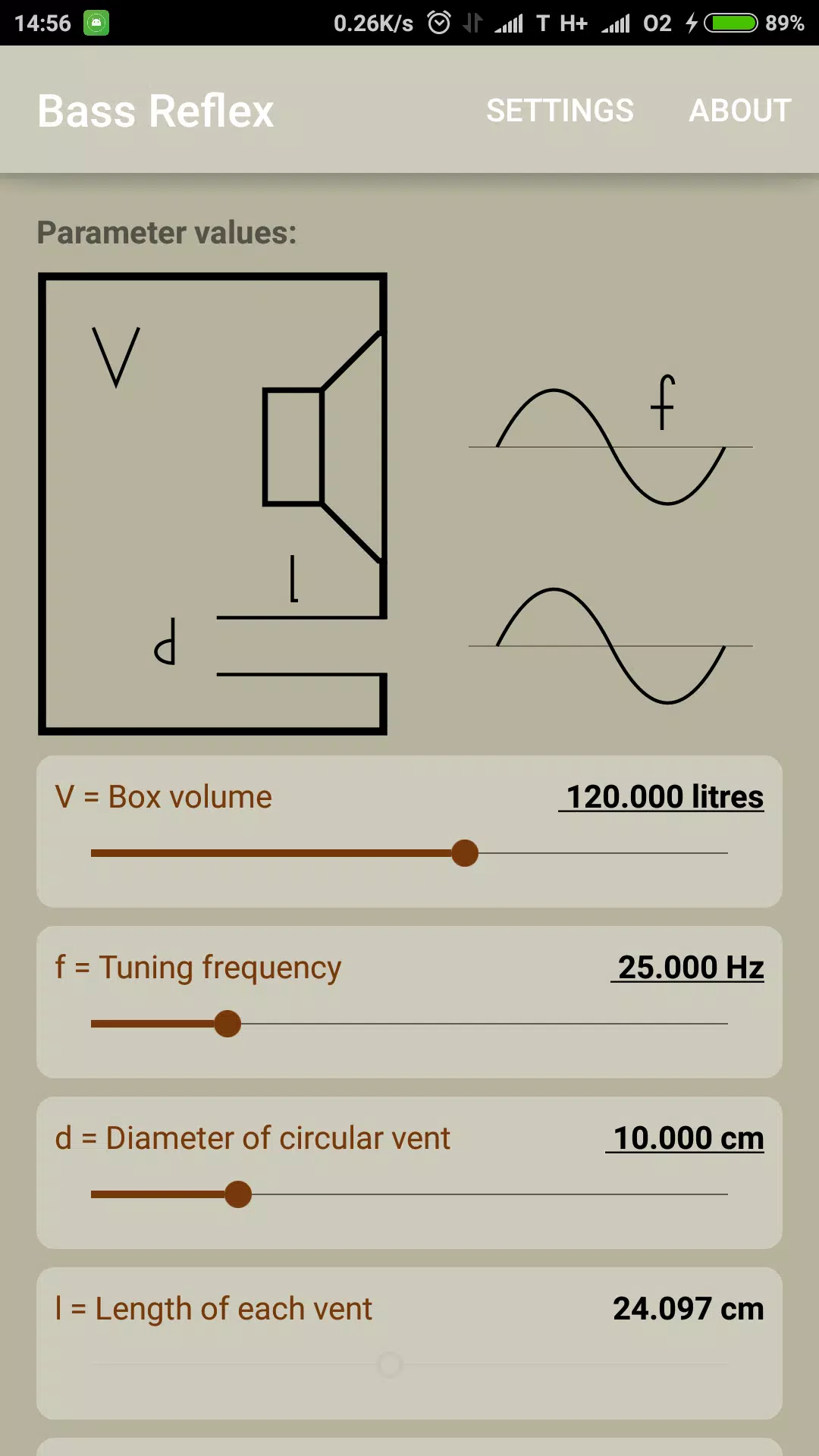


Unlike closed-box loudspeakers, which are nearly airtight, a bass reflex system has an opening called a port or vent cut into the cabinet, generally consisting of a pipe or duct (typically circular or rectangular cross section). The air mass in this opening resonates with the «springiness» of the air inside the enclosure in exactly the same fashion as the air in a bottle resonates when a current of air is directed across the opening. Another metaphor often used is to think of the air like a spring or rubber band. The frequency at which the box/port system resonates, known as the Helmholtz resonance, depends upon the effective length and cross sectional area of the duct, the internal volume of the enclosure, and the speed of sound in air. In the early years of ported speakers, speaker designers had to do extensive experimentation to determine the ideal diameter of the port and length of the port tube or pipe; however, more recently, there are numerous tables and computer programs that calculate, for a given size of cabinet, how large the port should be and how long the tube should be. Even with these programs, however, some experimentation with prototypes is still necessary to determine if the enclosure sounds good.
A small JVC speaker with a port.
If this vent air mass/box air springiness resonance is so chosen as to lie lower in frequency than the natural resonance frequency of the bass driver, an interesting phenomenon happens: the backwave of the bass driver sound emission is inverted in polarity for the frequency range between the two resonances. Since the backwave is already in opposite polarity with the front wave, this inversion brings the two emissions in phase (although the vent emission is lagging by one wave period) and therefore they reinforce each other. This has the useful purpose of producing higher output (for any given driver excursion compared to a closed box) or, conversely, a similar output with a smaller excursion (which means less driver distortion). The penalty incurred for this reinforcement is time smearing: in essence the vent resonance augments main driver output by imposing a «resonant tail» on it. For frequencies above the natural resonance of the driver, the reflex alignment has no influence. For frequencies below the vent resonance, polarity inversion is not accomplished, and backwave cancellation occurs. Furthermore, the driver behaves as though suspended in free air, as box air springiness is absent.
When speakers are designed for home use or for high-volume live performance settings (e.g., with bass amplifier speaker cabinets and PA system speakers and subwoofers), manufacturers often consider the advantages of porting (increased bass response, lower bass response, improved efficiency) to outweigh the disadvantages (port noise, resonance problems). The design is popular among consumers and manufacturers (speakers cabinets can be smaller and lighter, for more or less equivalent performance) but the increase in bass output requires close matching of driver, the enclosure, and port. Poorly matched reflex designs can have unfortunate characteristics or drawbacks, sometimes making them unsuitable for settings requiring high accuracy and neutrality of sound, e.g. studio monitor speakers for use by audio engineers in monitoring facilities, recording studios etc. However it is possible to design a bass reflex system that mostly overcomes these drawbacks; and quality bass reflex designs are commonly found in demanding environments across the world.
What Is The Difference Between Bass Reflex And Acoustic Suspension?
The bass reflex enclosure remains the most popular of all time. People love it for its excellent bass response and high output. However, there are reasons why people go for acoustic suspension while others prefer bass reflex systems.
Bass extension – This is a system’s ability to play low notes. Generally, bass reflex systems are more efficient when it comes to bass extension. However, the bass roll off begins somewhere between 24dB/octave. On the other hand, the sealed speaker starts to roll off at 12dB/Octave. This is a much more gentle roll-off compared to the bass reflex enclosure.
Distortion – Bass reflex systems are prone to more distortion, especially from the ports. But thanks to technology, research, and advanced manufacturing, this should no longer be a problem. On the other hand, acoustic suspension systems have better dampening, which reduces distortion.
Sizes – Acoustic suspension types come in smaller boxes. They fit perfectly in smaller rooms. However, bass reflex systems come in much larger boxes. They are ideal for bigger rooms for spacing reasons.
History[edit]
A small Keesonic Kub speaker. With the front grille removed, the port is visible between the two drivers.
The effect of the various speaker parameters, enclosure sizes and port (and duct) dimensions on the performance of bass reflex systems was not well understood until the early 1960s. Subsequently, pioneering analyses by A.N. Thiele, J.E. Benson and Richard H. Small presented the theoretical foundations for the synthesis of bass reflex loudspeaker systems to meet specified low-frequency performance criteria were developed into a series of «alignments» (sets of the relevant speaker parameters) that allowed designers to produce useful, predictable responses. Keele extended the design options by presenting a new set of 6th-order vented-box loudspeaker system alignments. All of these results made it possible for speaker manufacturers to design bass reflex loudspeakers to match various sizes of enclosures, and to match enclosures to given speakers with great predictability. Due to the physical electromechanical constraints, it is not possible to have a small speaker in a small enclosure producing extended bass response at high efficiencies (i.e., requiring only a low-powered amplifier). It is possible to have two of these attributes, but not all; this has been termed Hofmann’s Iron Law after J. Anton Hofmann of KLH’s summary (with Henry Kloss) of Edgar Villchur work years earlier. The sound pressure produced depends upon the efficiency of the speaker, the mechanical or thermal power handling of the driver, the power input and the size of the driver.
Bass reflex vent.